
click here to download B.E. ELECTRICAL AND ELECTRONICS ENGINEERING
EE339 - POWER SYSTEM ANALYSIS
Anna University
B.E./B.Tech. DEGREE EXAMINATION, APRIL/MAY 2011
Sixth Semester
EE 2351 — POWER SYSTEM ANALYSIS (Regulation 2008)
Time : Three hours
Maximum : 100 marks
Answer ALL questions
PART A — (10 × 2 = 20 marks)
1. Draw a simple per-phase model for a cylindrical rotor synchronous machine.
2. What are the advantages of per unit system?
3. What is Jacobian matrix?
4. What is a slack bus?
5. Mention the objectives of short circuit analysis.
6. Write down the balanced and unbalanced faults occurring in a power system.
7. What is sequence network?
8. Write the symmetrical components of a three phase system?
9. Define critical clearing angle.
10. Write swing equation.
PART B — (5 × 16 = 80 marks)
11. (a) (i) With the help of single line diagram, explain the basic components of a power system. (8)
(ii) Write detailed notes about the per-phase model of a three phase transformer. (8)
Or
(b) Draw the impedance diagram for the electric power system shown in figure 11 (b) showing all impedance in per unit on a 100-MVA base. Choose 20-kV as the voltage base for generator. The three-phase power and line-line ratings are given below. (16)
G1 : 90 MVA 20 kV X = 9%
T1 : 80 MVA 20/200 kV X = 16% T2 : 80 MVA 200/20kV X = 20% G2 : 90 MVA 18 kV X = 9%
Line : 200 kV X = 120
Load : 200 kV, S = 48 MW + j64Mvar
Fig. 11. (b)
12. (a) With neat flow chart explain the computational procedure for load flow solution using fast decoupled method when the system contains all types of buses. (16)
Or
(b) Explain the step by step computational procedure for the Gauss-Seidel method of load flow studies. (16)
13. (a) Explain symmetrical fault analysis using Z-bus matrix with neat flow chart. (16)
Or
(b) A 11 kV, 100 MVA alternator having a sub-transient reactance of 0.25 pu is supplying a 50 MVA motor having a sub-transient reactance of 0.2 pu through a transmission line. The line reactance is 0.05 pu on a base of 100 MVA. The motor is drawing 40 MW at 0.8 p.f. leading with a terminal voltage of 10.95 kV when a 3-phase fault occurs at the generator terminals. Calculate the total current in generator and motor under fault conditions. (16)
14. (a) What are the assumptions to be made in short circuit studies? Deduce and thaw the sequence network for a line to line fault at the terminals of an unloaded generator. (16)
Or
(b) Two 11 kV, 20 MVA, three phase, star connected generators operate in parallel as shown in Figure 14. (b) ; the positive, negative and zero sequence reactance’s of each being, respectively, j0.l8, j0.15, j0.10 pu. The star point of one of the generators is isolated and that of the other is earthed through a 2.0 ohms resistor. A single line to ground fault occurs at the terminals of one of the generators. Estimate
(i) the fault current,
(ii) current in grounding resistor, and
(iii) the voltage across grounding resistor. (16) Fig. 14. (b)
15. (a) Describe the Runge-Kutta method of solution of swing equation for multi-machine systems. (16)
Or
(b) Derive an expression for the critical clearing angle and clearing time. (16)
Anna Univeristy
B.E./B.Tech. DEGREE EXAMINATION
NOVEMBER/DECEMBER 2011.
Sixth Semester
Electrical and Electronics Engineering
EE 2351 — POWER SYSTEM ANALYSIS
(Regulation 2008)
Sixth Semester
Electrical and Electronics Engineering
EE 2351 — POWER SYSTEM ANALYSIS
(Regulation 2008)
Time : Three hours Maximum : 100 marks
Answer ALL questions.
Answer ALL questions.
PART A — (10 × 2 = 20 marks)
1. What is single line diagram?
2. How are the loads represented in reactance or impedance diagram?
3. What are the different types of buses in power systems? What are the quantities specified in each bus?
4. How are the disadvantages of Newton–Raphson method overcome?
5. What is the need for short circuit studies?
6. List the various types of shunt and series faults.
7. Define negative sequence impedance.
8. Name the faults which do not have zero sequence currents flowing.
9. Give an expression for swing equation. Explain each term along with their units.
10. State equal area criterion.
B.E./B.Tech. DEGREE EXAMINATION,APRIL/MAY 2010
VI - SEMESTER
B.E. ELECTRICAL AND ELECTRONICS ENGINEERING
EE339 - POWER SYSTEM ANALYSIS
Time: 3hrs Max Marks: 100
Answer all Questions
PART – A (10 x 2 = 20 Marks)
1. What is the need for system analysis in planning and operation of power system?
2. How are the base values chosen in per unit representation of a power system?
3. Draw the equivalent circuit of a transformer with off-nominal tap ratio and admittance .
4. Define bus incidence matrix.
5. Mention two objectives of short circuit analysis.
6. Draw the zero sequence network of a star connected generator with zero sequence impedance Zgo when the neutral is grounded through an impedance Zn.
7. What are the three classes of buses of a power system used in power flow analysis? What are the quantities to be specified and to be computed for each class during power flow solution?
8. Compare Gauss-Seidel method and Newton – Raphson method with respect to
number of iterations taken for convergence and memory requirement.
9. Define critical clearing time.
10. Write the power-angle equation of a synchronous machine connected to an infinite bus and also the expression for maximum power transferable to the bus.
PART B (5 x 16 = 80 Marks)
11. Obtain the per unit impedance (reactance) diagram of the power system
Generator No.1: 20 MVA, 10.5 KV, X'' = 1.4 ohms, Xn1= 0.5 ohm
Generator No.2: 10 MVA, 6.6 KV, X"= 1.2 ohms, Xn2 = 0.5 ohm
Transformer T1 (3 phase): 10 MVA, 33/11 kV, X = 15.2 ohms per phase on high tension side.
Transformer T2 (3 phase) : 10 MVA, 33/6.2 kV, X= 16 ohms per phase on high tension side.
Transmission line: 22.5 ohms / phase.
Choose a common base of 20 MVA
12.a) Determine Z bus using bus impedance matrix building algorithm by adding the lines as per increasing element number. The reactance diagram of the system is shown in
(OR)
12.b) Explain the modelling of Generator, Load and Transmission line for short circuit, power flow and stability studies.
13.a) Derive the formula for fault current, fault-bus voltages and current through the lines for a 3 phase symmetrical fault at a bus in a power system using Z bus. State the assumptions made in the derivation.
(OR)
13.b) A single line to ground fault occurs on bus 4 of the system shown in Figure. Q.13(b)
(i) Draw the sequence networks.
Generator 1 & 2 : 100 MVA, 20kV with X1 = X2 = 20%, X0 = 4%, Xn = 5%
Transformer 1 & 2 : 100 MVA, 20kV/345kV. X leakage = 8% on 100 MVA.
Transmission line: X1 = X2 =15% and X0 =50% on a base of 100 MVA, 20kV
14.a) Explain clearly the algorithmic steps for solving load flow equations using Newton – Raphson method (polar form) when the system contains all types of buses. Assume that the generators at the P-V buses have enormous Q limits and hence Q limits need not be checked.
(OR)
14.b) The system data for a load flow problem are given in Table 1 and Table 2.
(i) Compute Y bus
(ii) Determine bus voltages at the end of 1st iteration by Gauss-Seidel method. Take acceleration factor as 1.6.
Bus Code of Lines Admittance (p.u)
1-2 2-j8
1-3 1-j4
2-3 0.6-j2.6
TABLE – 1 Line Data
Bud Code P Demand in p.u Q Demand in p.u V, p.u Remarks
1 - - 1.06?0 Slack
2 0.5 0.2 - PQ
3 0.4 0.3 - PQ
TABLE – 2 Bus Data
15.a)i) Write the swing equation describing the rotor dynamics of a synchronous machine connected to infinite bus through a double circuit transmission line.
ii) Explain the step-wise procedure of determining the swing curve of the above system using Modified Euler's method.
(OR)
15.b) In the system shown in Fig, Q. 15(b) a 3 phase fault occurs at point P closer to bus 2.
Find the critical clearing angle for clearing the fault with simultaneous opening of the breakers 1 & 2. The reactance values of the various components are Xg = 0.15 p.u Xtr=0.1 p.u, XL1 = 0.5 p.u, XL2 = 0.4 p.u. The generator is delivering 1.0 p.u power at the instant preceding the fault.
Anna University
B.E./B.Tech. DEGREE EXAMINATION, APRIL/MAY 2011
Sixth Semester
EE 2351 — POWER SYSTEM ANALYSIS (Regulation 2008)
Time : Three hours
Maximum : 100 marks
Answer ALL questions
PART A — (10 × 2 = 20 marks)
1. Draw a simple per-phase model for a cylindrical rotor synchronous machine.
2. What are the advantages of per unit system?
3. What is Jacobian matrix?
4. What is a slack bus?
5. Mention the objectives of short circuit analysis.
6. Write down the balanced and unbalanced faults occurring in a power system.
7. What is sequence network?
8. Write the symmetrical components of a three phase system?
9. Define critical clearing angle.
10. Write swing equation.
PART B — (5 × 16 = 80 marks)
11. (a) (i) With the help of single line diagram, explain the basic components of a power system. (8)
(ii) Write detailed notes about the per-phase model of a three phase transformer. (8)
Or
(b) Draw the impedance diagram for the electric power system shown in figure 11 (b) showing all impedance in per unit on a 100-MVA base. Choose 20-kV as the voltage base for generator. The three-phase power and line-line ratings are given below. (16)
G1 : 90 MVA 20 kV X = 9%
T1 : 80 MVA 20/200 kV X = 16% T2 : 80 MVA 200/20kV X = 20% G2 : 90 MVA 18 kV X = 9%
Line : 200 kV X = 120
Load : 200 kV, S = 48 MW + j64Mvar
Fig. 11. (b)
12. (a) With neat flow chart explain the computational procedure for load flow solution using fast decoupled method when the system contains all types of buses. (16)
Or
(b) Explain the step by step computational procedure for the Gauss-Seidel method of load flow studies. (16)
13. (a) Explain symmetrical fault analysis using Z-bus matrix with neat flow chart. (16)
Or
(b) A 11 kV, 100 MVA alternator having a sub-transient reactance of 0.25 pu is supplying a 50 MVA motor having a sub-transient reactance of 0.2 pu through a transmission line. The line reactance is 0.05 pu on a base of 100 MVA. The motor is drawing 40 MW at 0.8 p.f. leading with a terminal voltage of 10.95 kV when a 3-phase fault occurs at the generator terminals. Calculate the total current in generator and motor under fault conditions. (16)
14. (a) What are the assumptions to be made in short circuit studies? Deduce and thaw the sequence network for a line to line fault at the terminals of an unloaded generator. (16)
Or
(b) Two 11 kV, 20 MVA, three phase, star connected generators operate in parallel as shown in Figure 14. (b) ; the positive, negative and zero sequence reactance’s of each being, respectively, j0.l8, j0.15, j0.10 pu. The star point of one of the generators is isolated and that of the other is earthed through a 2.0 ohms resistor. A single line to ground fault occurs at the terminals of one of the generators. Estimate
(i) the fault current,
(ii) current in grounding resistor, and
(iii) the voltage across grounding resistor. (16) Fig. 14. (b)
15. (a) Describe the Runge-Kutta method of solution of swing equation for multi-machine systems. (16)
Or
(b) Derive an expression for the critical clearing angle and clearing time. (16)
Anna Univeristy
B.E./B.Tech. DEGREE EXAMINATION
NOVEMBER/DECEMBER 2011.
Sixth Semester
EE 2351 — POWER SYSTEM ANALYSIS
(Regulation 2008)
Time : Three hours Maximum : 100 marks
Answer ALL questions.
PART A — (10 × 2 = 20 marks)
1. What is single line diagram?
2. How are the loads represented in reactance or impedance diagram?
3. What are the different types of buses in power systems? What are the quantities specified in each bus?
4. How are the disadvantages of Newton–Raphson method overcome?
5. What is the need for short circuit studies?
6. List the various types of shunt and series faults.
7. Define negative sequence impedance.
8. Name the faults which do not have zero sequence currents flowing.
9. Give an expression for swing equation. Explain each term along with their units.
10. State equal area criterion.

12. (a) The one line diagram of three bus power system is shown in fig. Q.
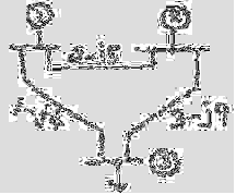
Fig. Q. 12 (a)
Bus 1: Slack bus Especified = 1.05∠0°
Bus 2: PV bus |E|specified = 1.2 pu., PG = 3 p.u.
Bus 3: PQ bus, PL = 4 p.u. QL=2 p.u.
Carry out one iteration of load flow solution by Gauss-Seidel method.
Take Q limits of generator 2 as 0≤Q≤ 4. Take α =1.
Or
(b) (i) Draw the flow chart of fast decoupled load flow method. (10)
(ii) Briefly explain the importance of power flow analysis. (6)
13. (a) Figure Q.13 (a) shows a generating station feeding a 132 KV system.
Determine the total fault current, fault level and fault current
supplied by each alternator for a 3-phase fault at the receiving end
bus. The line is 200 km long. Fig. Q. 13 (a) give below

Or
14(b) A 30 MVA. 11 KV generator has ZI=Z2=j0.2 p.u, Z0=j0.05 p.u. A line to
ground fault occurs on the generator terminals. Find the fault
current and line to line voltages during limit conditions. Assume that
the generator neutral is solidly grounded and that the generator is
operating at no load and at rated voltage at the occurrence of fault. (16)
15. (a) (i) A generator is operating at 50 Hz delivers 1 p.u. power to an
infinite bus through a transmission circuit in which resistance
is ignored. A fault takes place reducing the maximum power
transferable to 0.5 p.u. whereas before the fault, this power was
2.0 p.u. and after the clearance of the fault, it is 1.5 p.u. By the
use of equal area criterion, determine the critical clearing angle.(10)
(ii) Discuss the methods by which the transient stability can be
improved. (6)
Or
(b) Derive the swing equation of a single machine connected to an
infinite bus system and explain the steps of solution by Runge-Kutta
method. (16)
————————


.jpg)


1 comments:
if the link may broken ,comment here to get full documents
Post a Comment